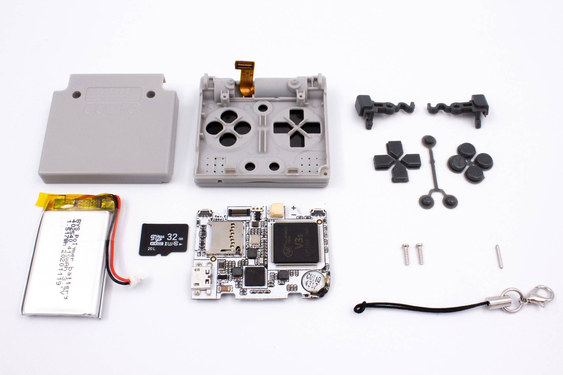
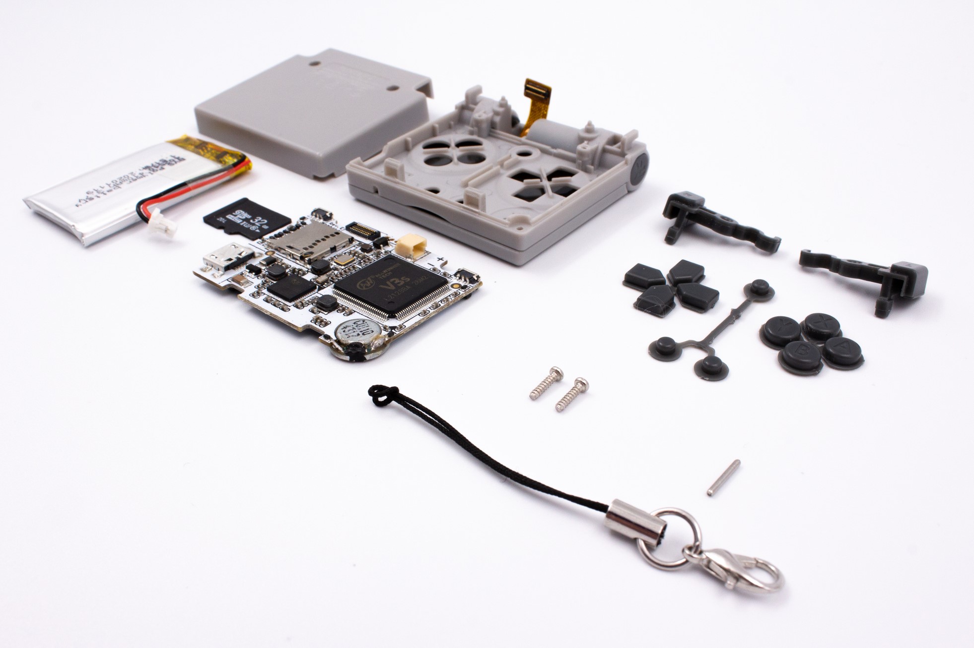
Teardown
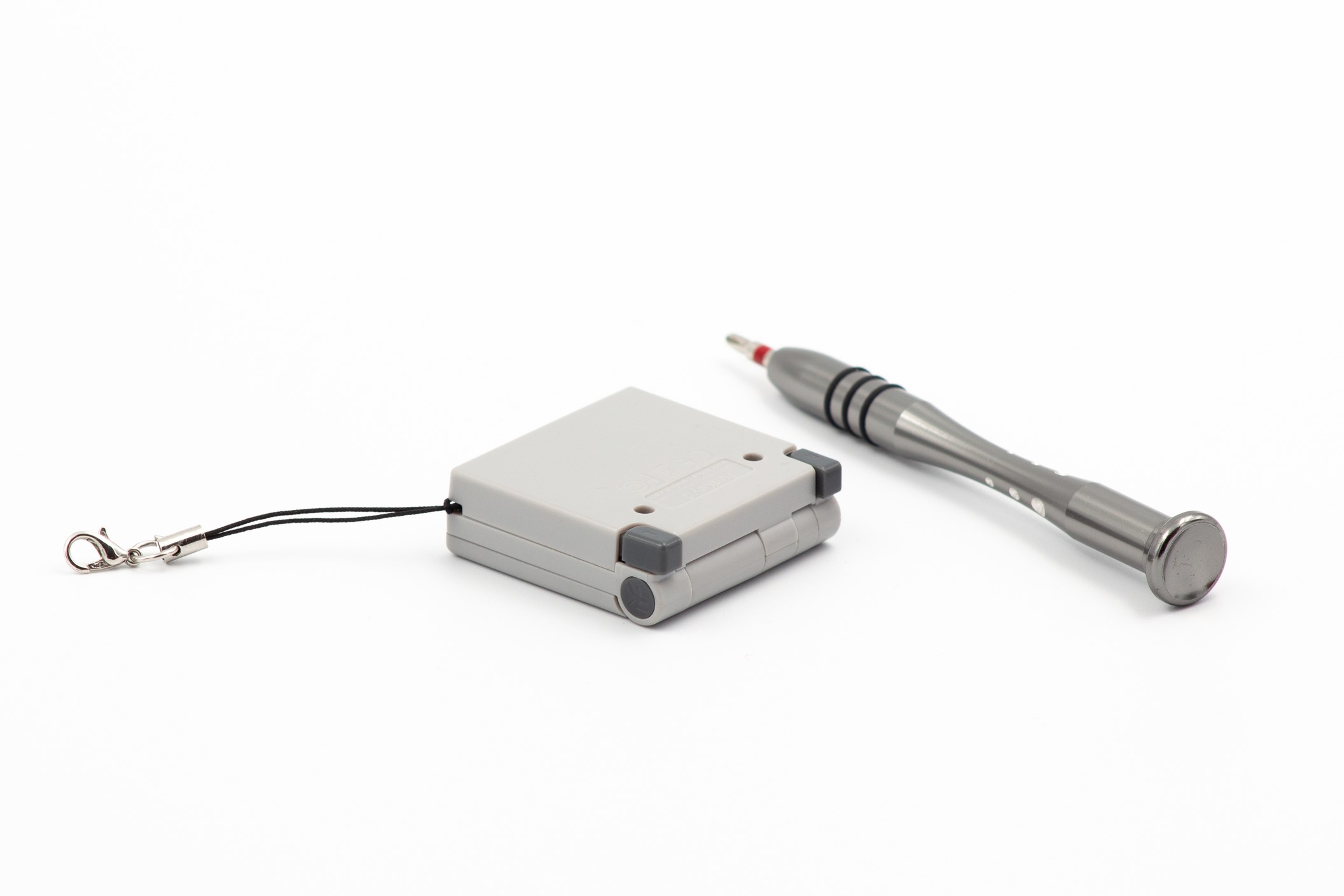
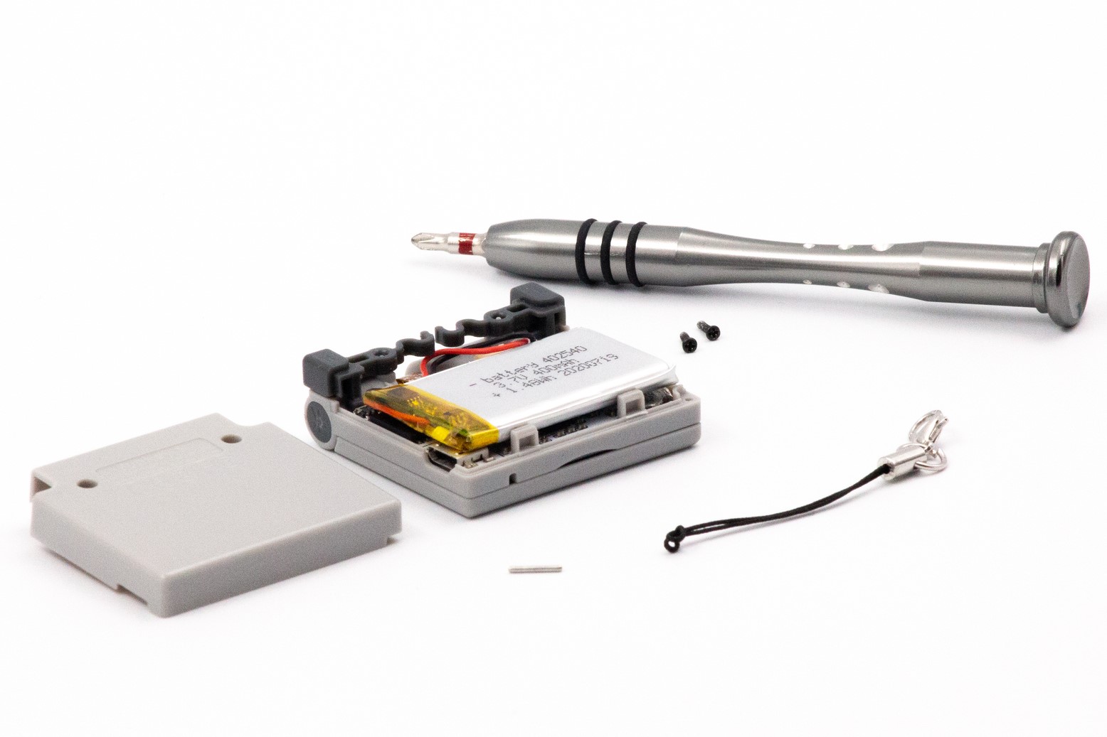
The FunKey S teardown was designed to be pretty straightforward. It only require a standard Phillips screwdriver (PH0) and tweezers.
Note
FunKey Project is not responsible for any damage done to your console during a teardown.
STEP 1 - Removing the screws
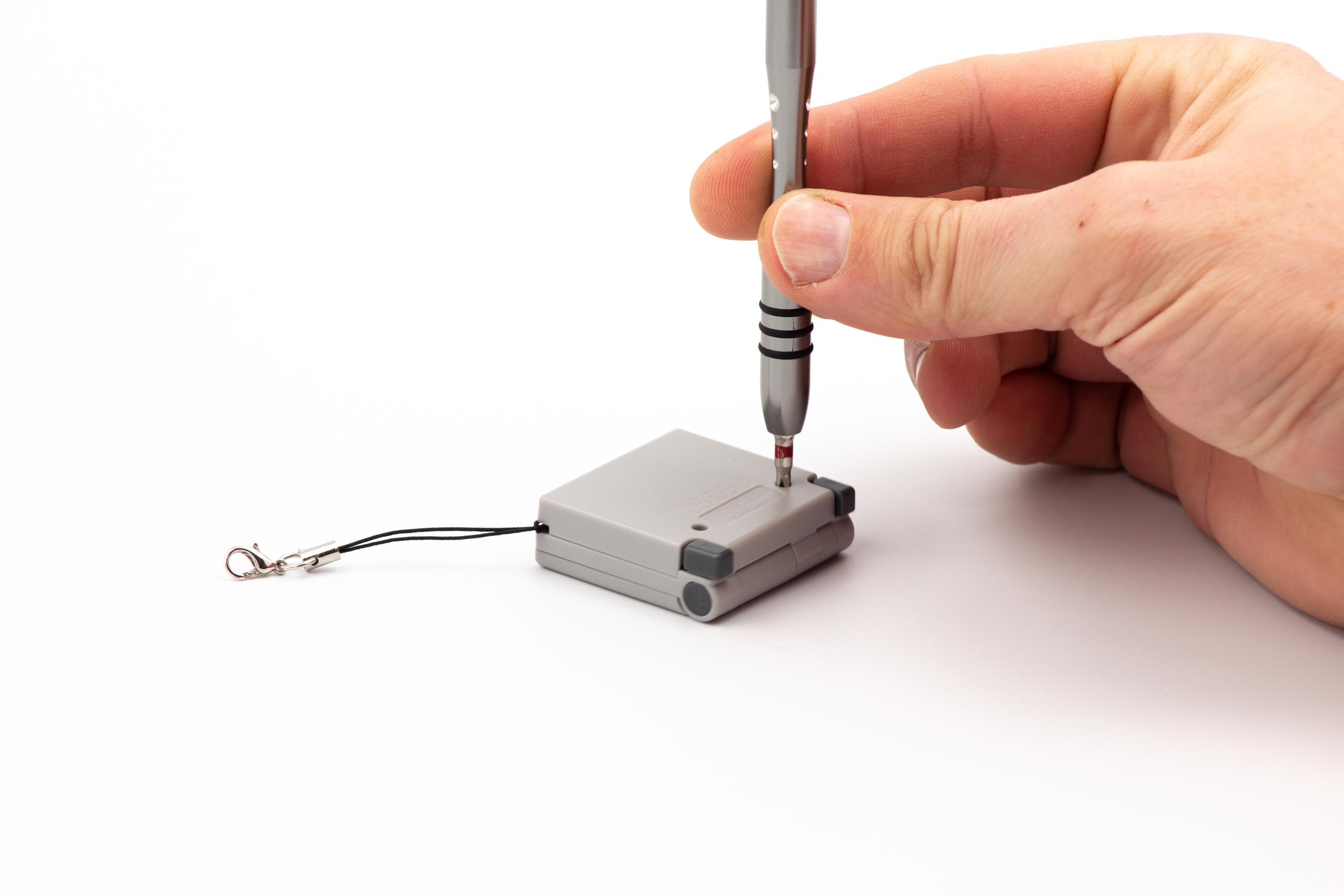
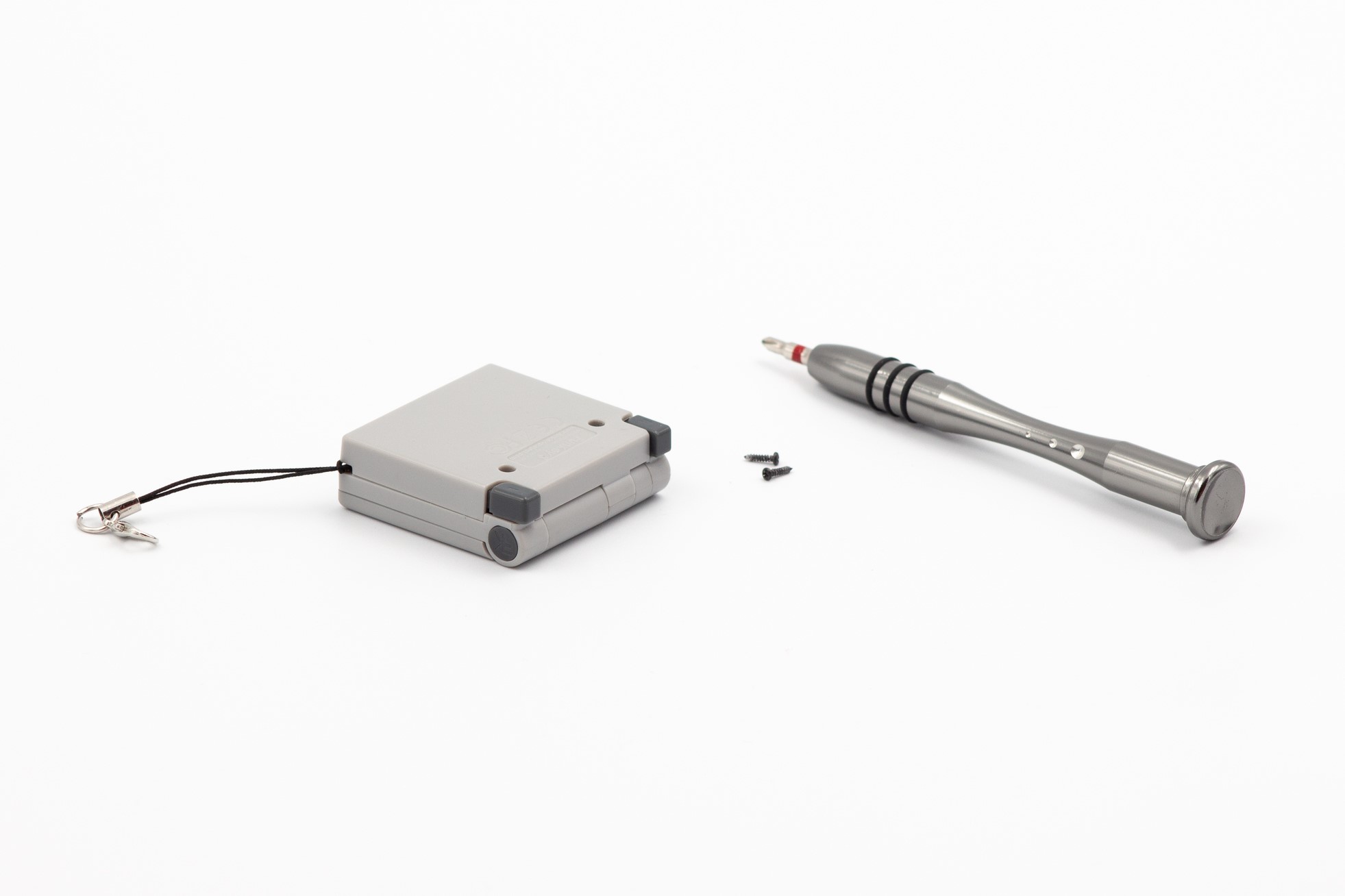
Using a standard Phillips PH0 screwdriver, remove the 2 screws on the back of your FunKey S.
Warning
Be careful to use the correct screwdriver head size and type to prevent damaging the screws (do not use JIS screwdrivers). FunKey Project is not responsible for replacing damaged screws.
STEP 2 - Opening up the console
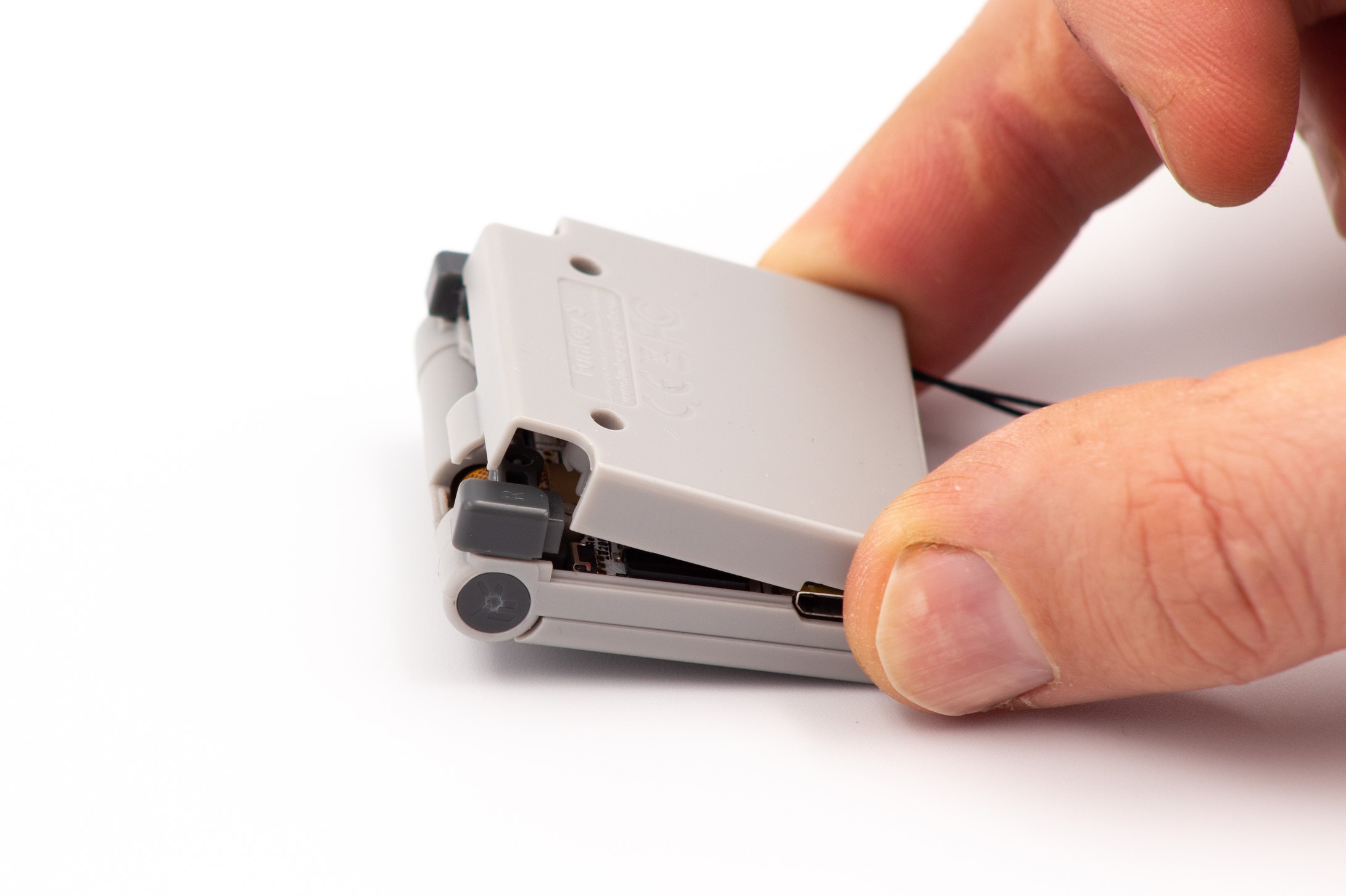
Carefully remove the plastic back of the console by pulling up the hinge side first
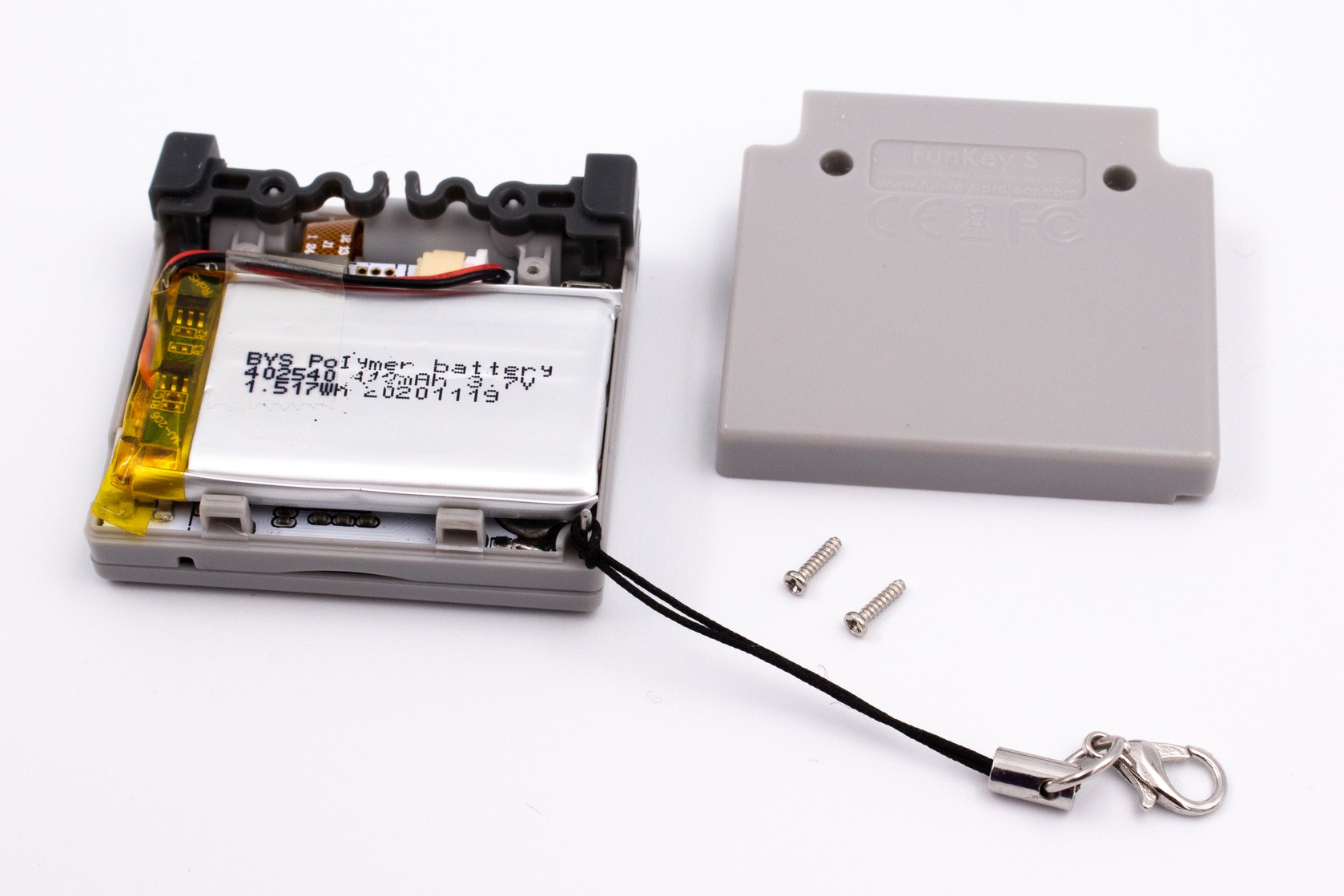
STEP 3 - Removing the keychain lanyard
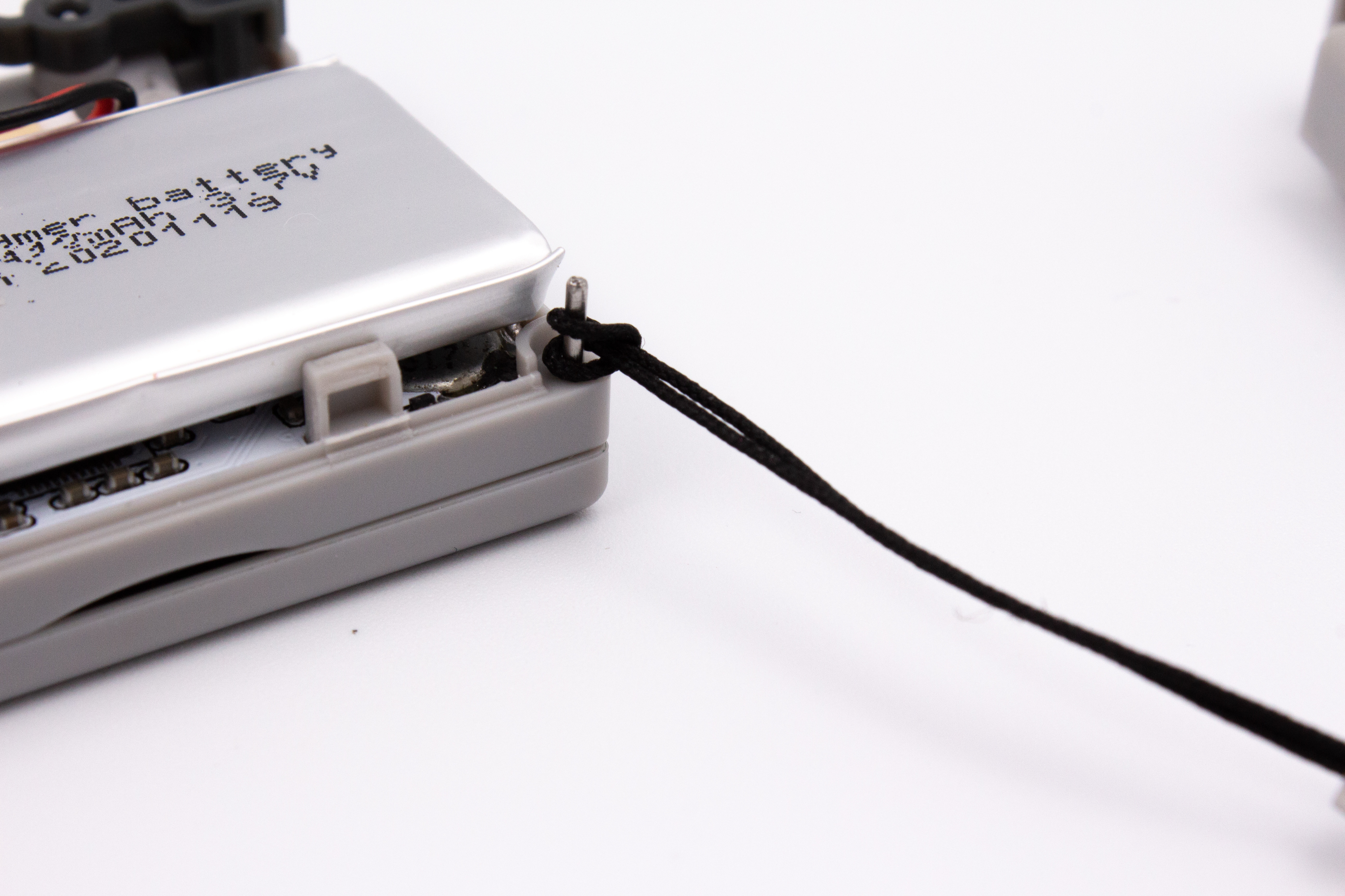
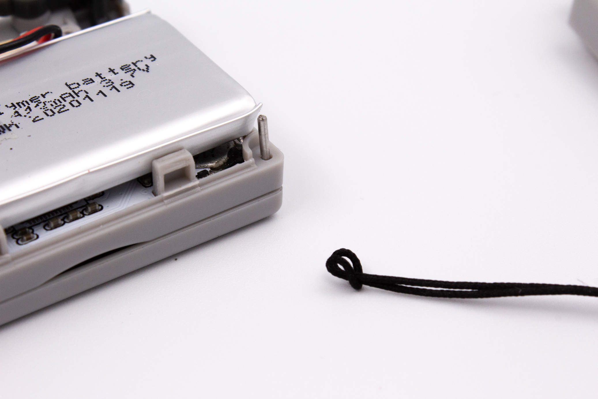
Carefully remove the keychain lanyard and its axis by pulling gently (it may fall off when opening).
Warning
The axis is a small part, be careful not to loose it.
STEP 4 - Removing the LR buttons
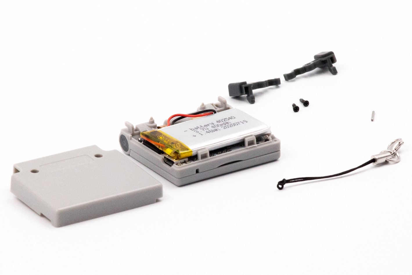
Carefully remove the L/R plastic buttons by gently pulling them out of their axis.
Warning
Be careful not to damage the L/R switches on the circuit board!
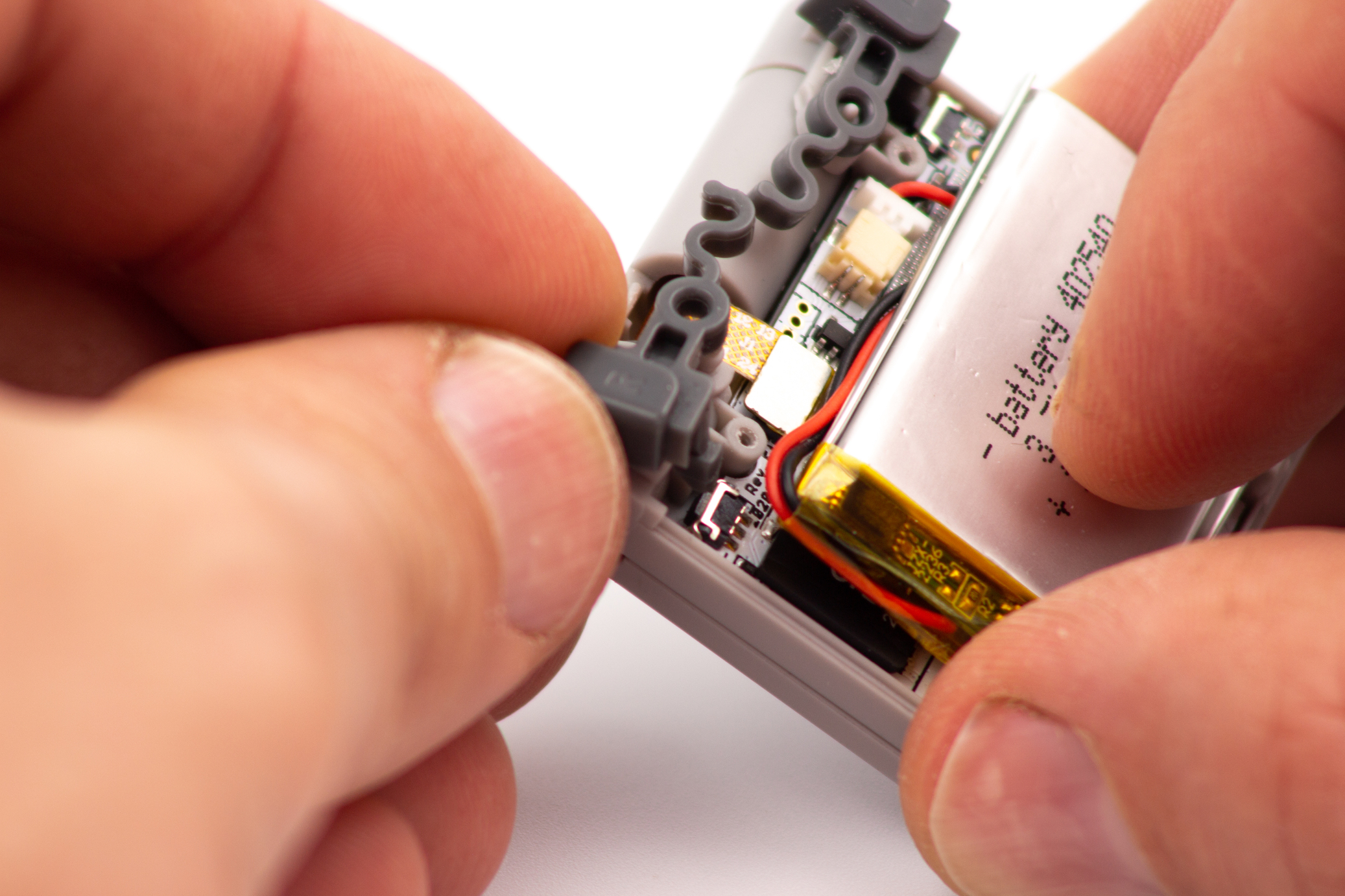
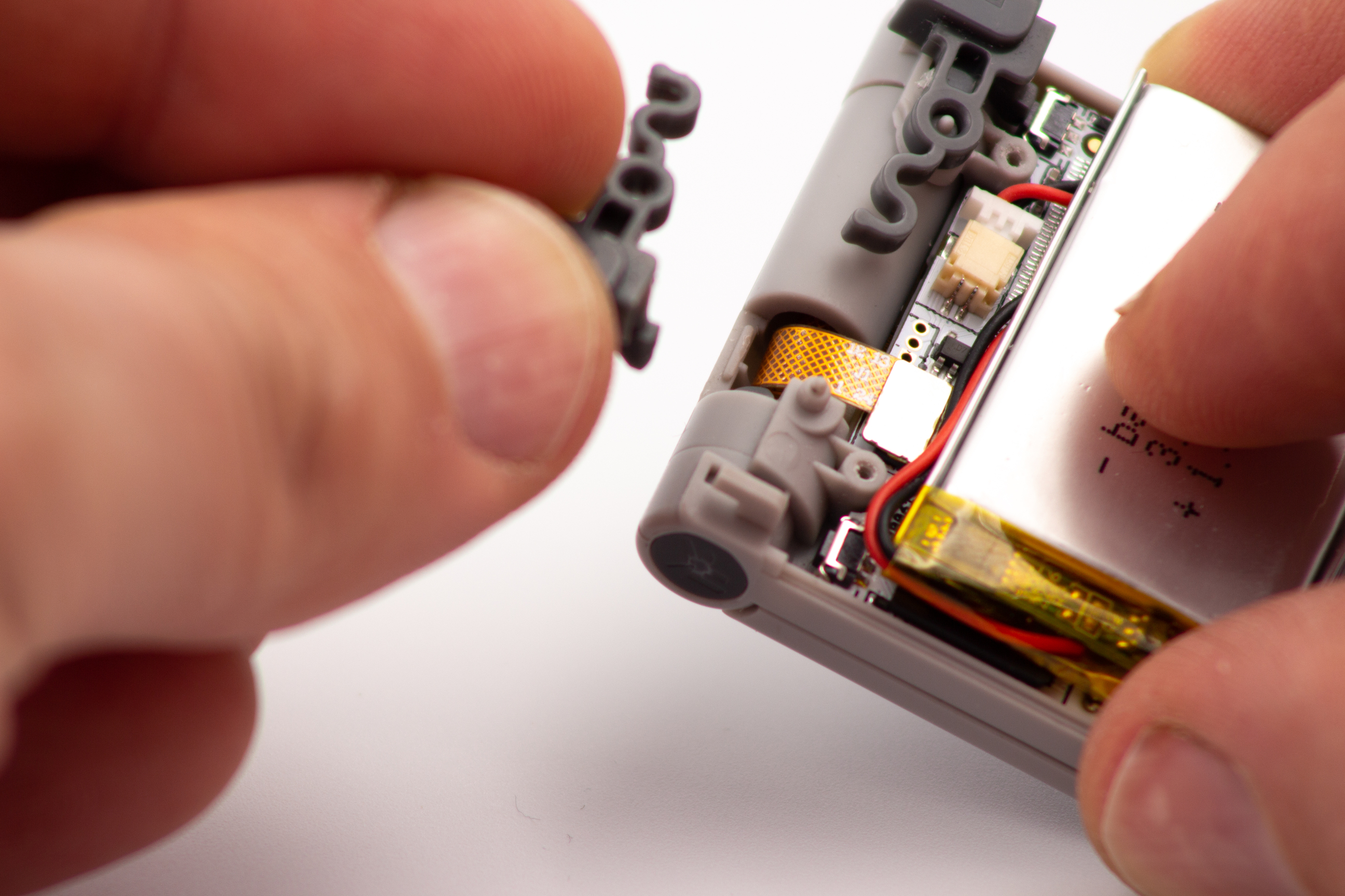
STEP 5 - Unplugging the battery
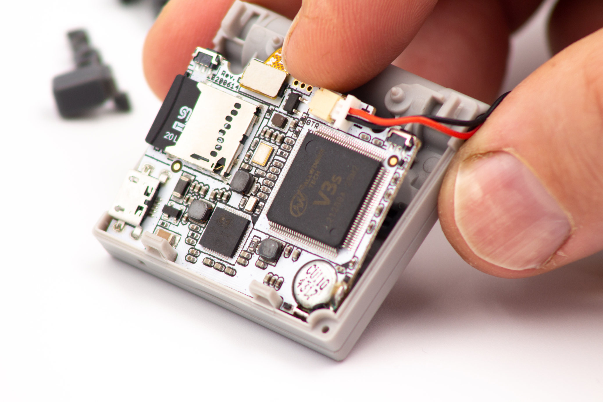
![]()
Lift the battery and pull gently by the top of the circuit board to unplug the battery. The battery may be stuck to the processor with double-sided adhesive, it's perfectly normal if you have to lift with a bit of force to unstick it.
Warning
Be sure to pull on the connector and NOT the wires when removing the battery. It is recommended to use tweezers.
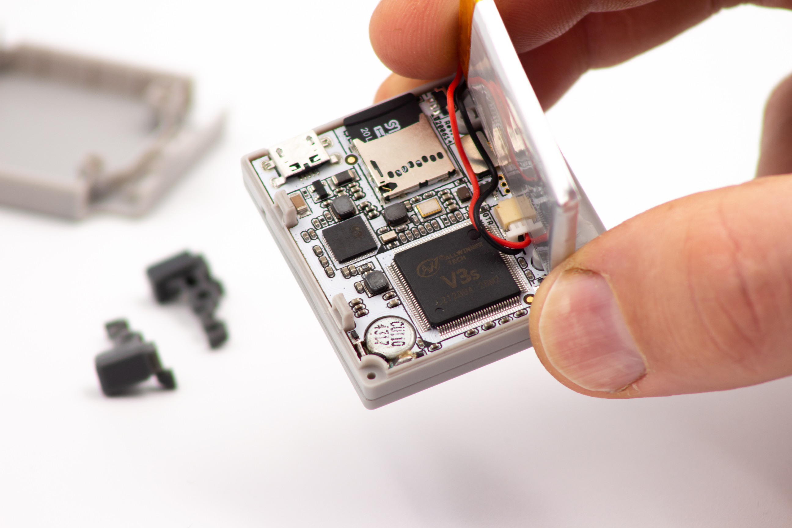
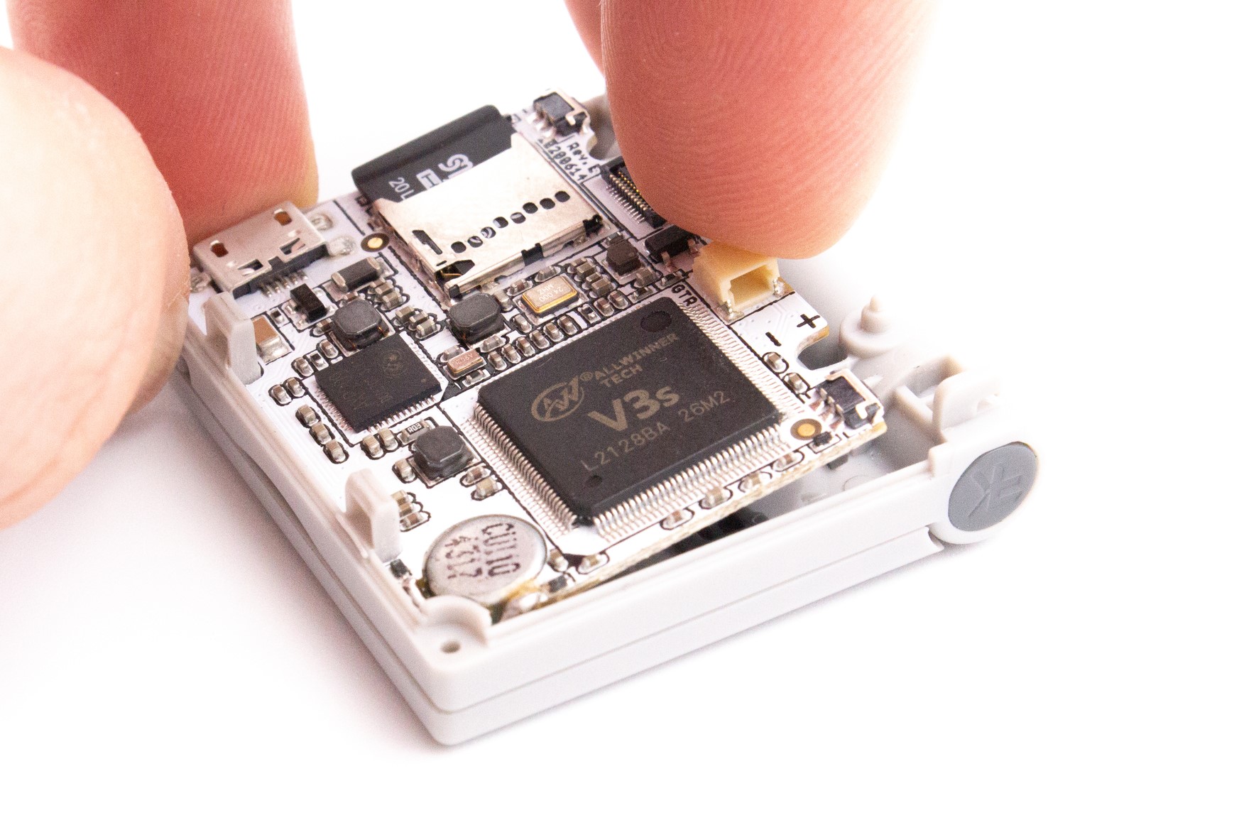
STEP 6 - Unplugging the screen
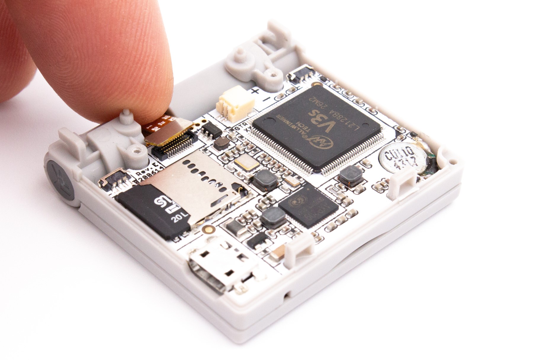
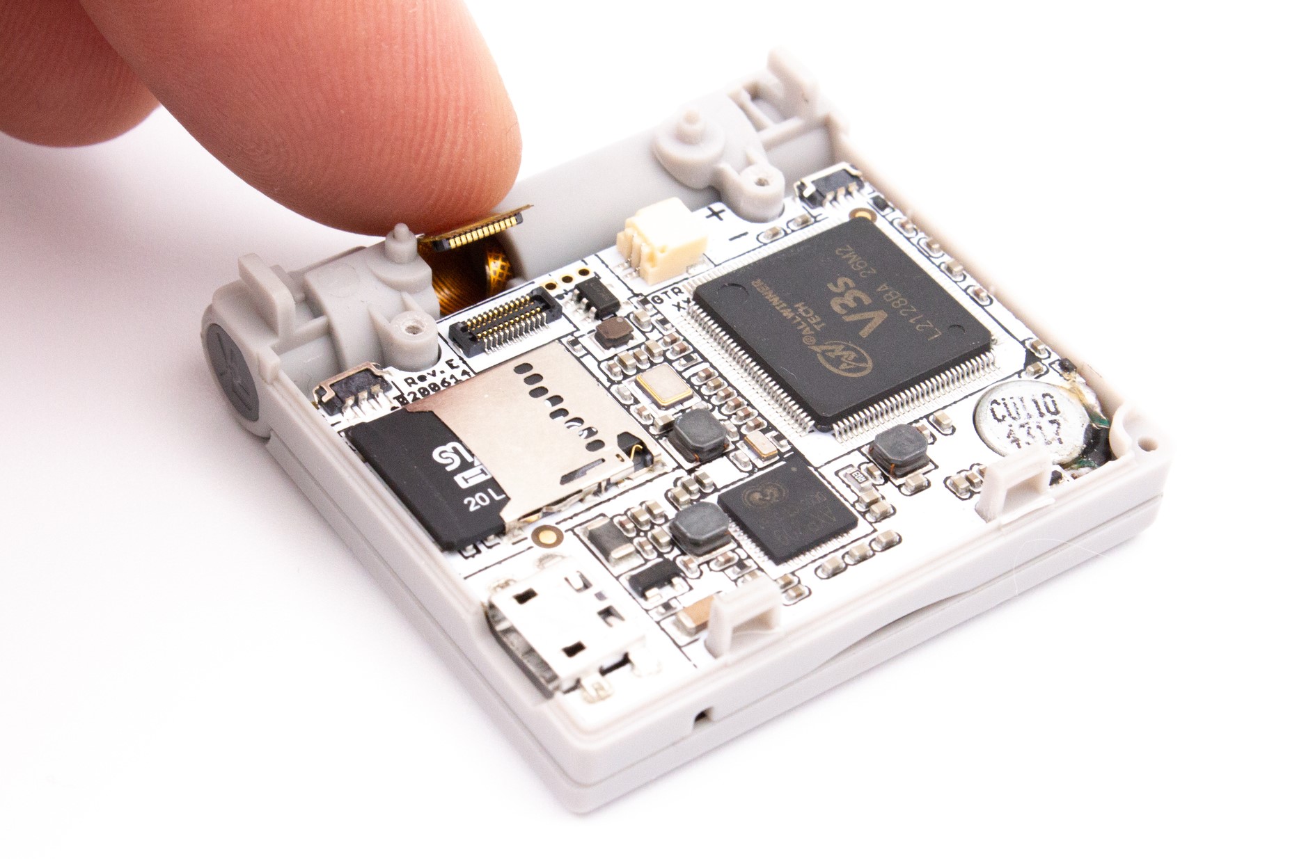
Now that you have access to the circuit board, you can unplug the screen.
Warning
This connector is fragile, unplug it vertically without force. It is recommended to use tweezers.
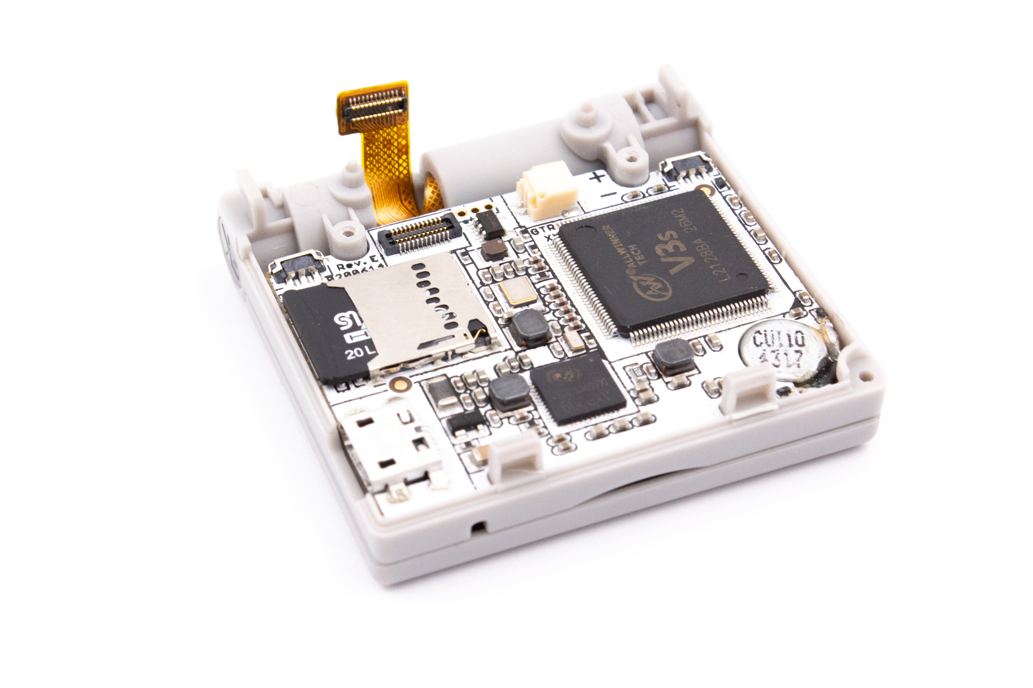
STEP 7 - Removing the circuit board
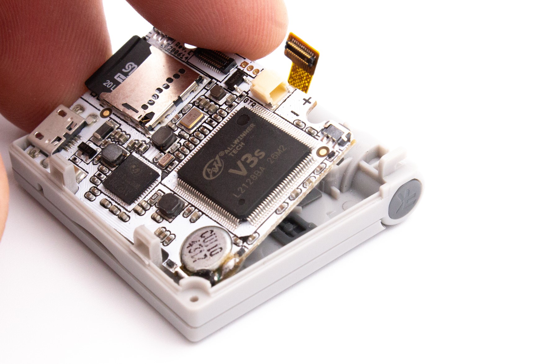
By grabbing it by the hinge side, gently pull up the circuit board from the plastic casing.
STEP 8 - Removing the micro-SD card
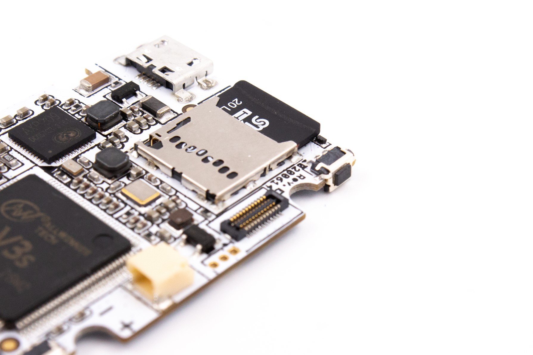
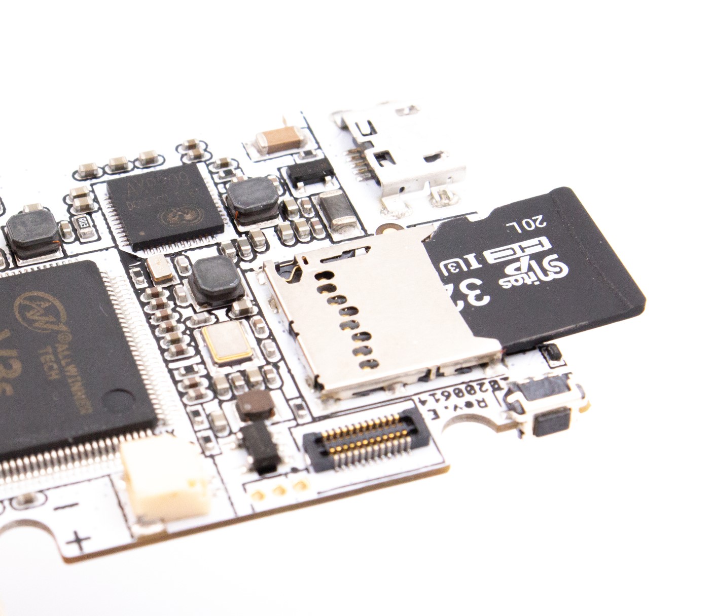
Remove the micro-SD card from its socket.
Note
You may need to use some tweezers and pull with some strength in order to remove the micro-SD card from its socket, as it is strongly inserted to prevent loose connections.
Warning
During this step be very careful not to damage the L/R switches. Never put the PCB on a flat surface (this would apply force on the LR switches) and do not grab the PCB by these switches.
STEP 9 - Removing the buttons
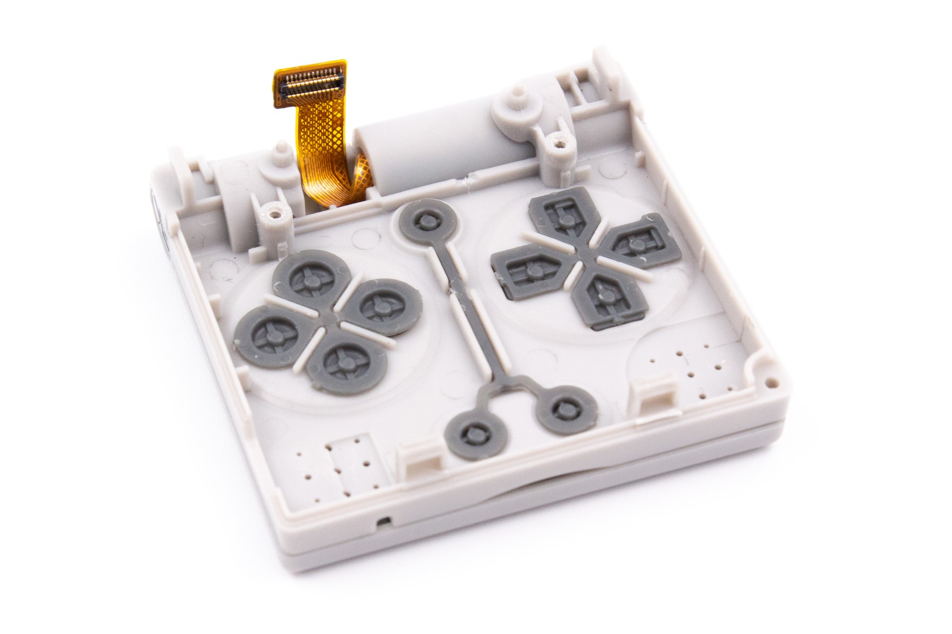
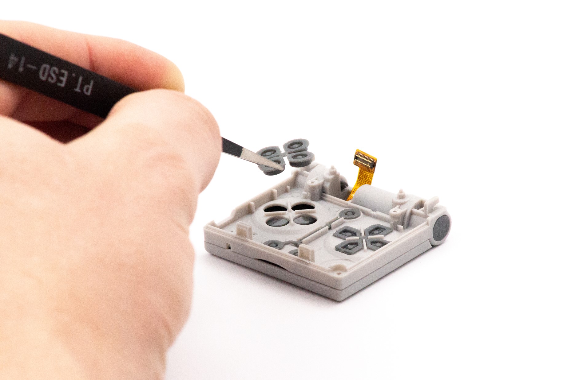
Remove the buttons from their socket. It is recommended to use tweezers.
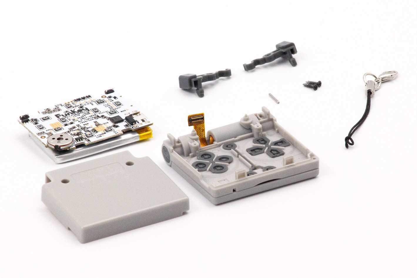
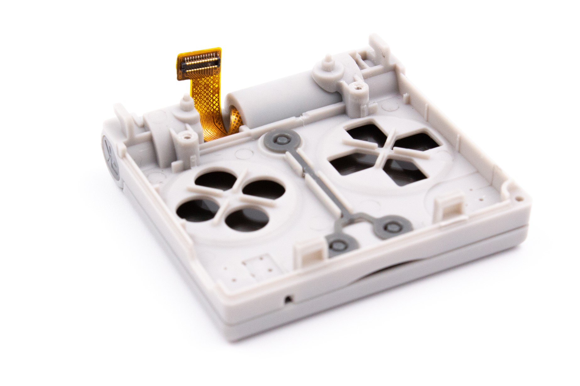
STEP 10 - Teardown complete
Good job the teardown is complete!
STEP 11 - Reassembly
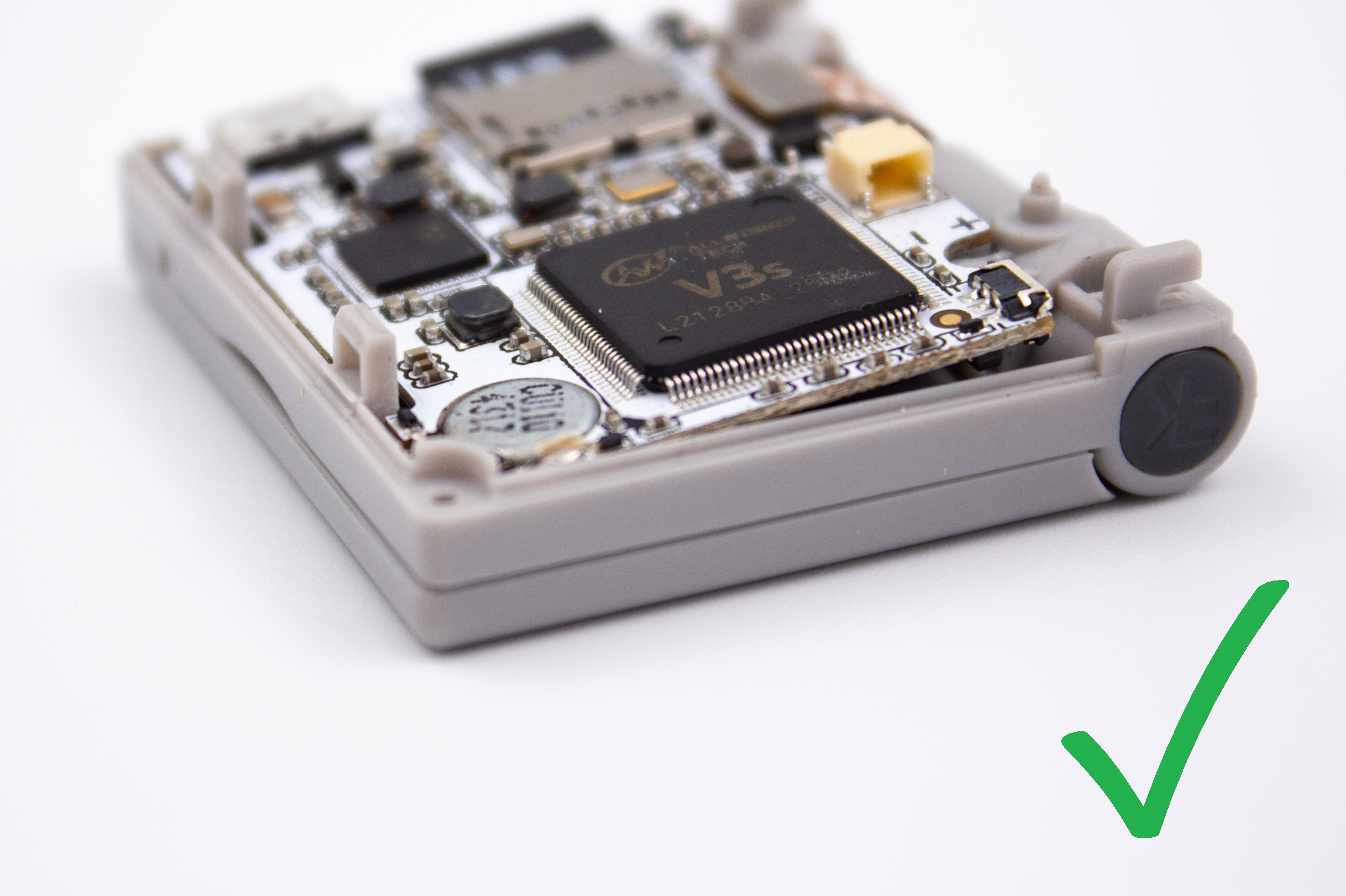
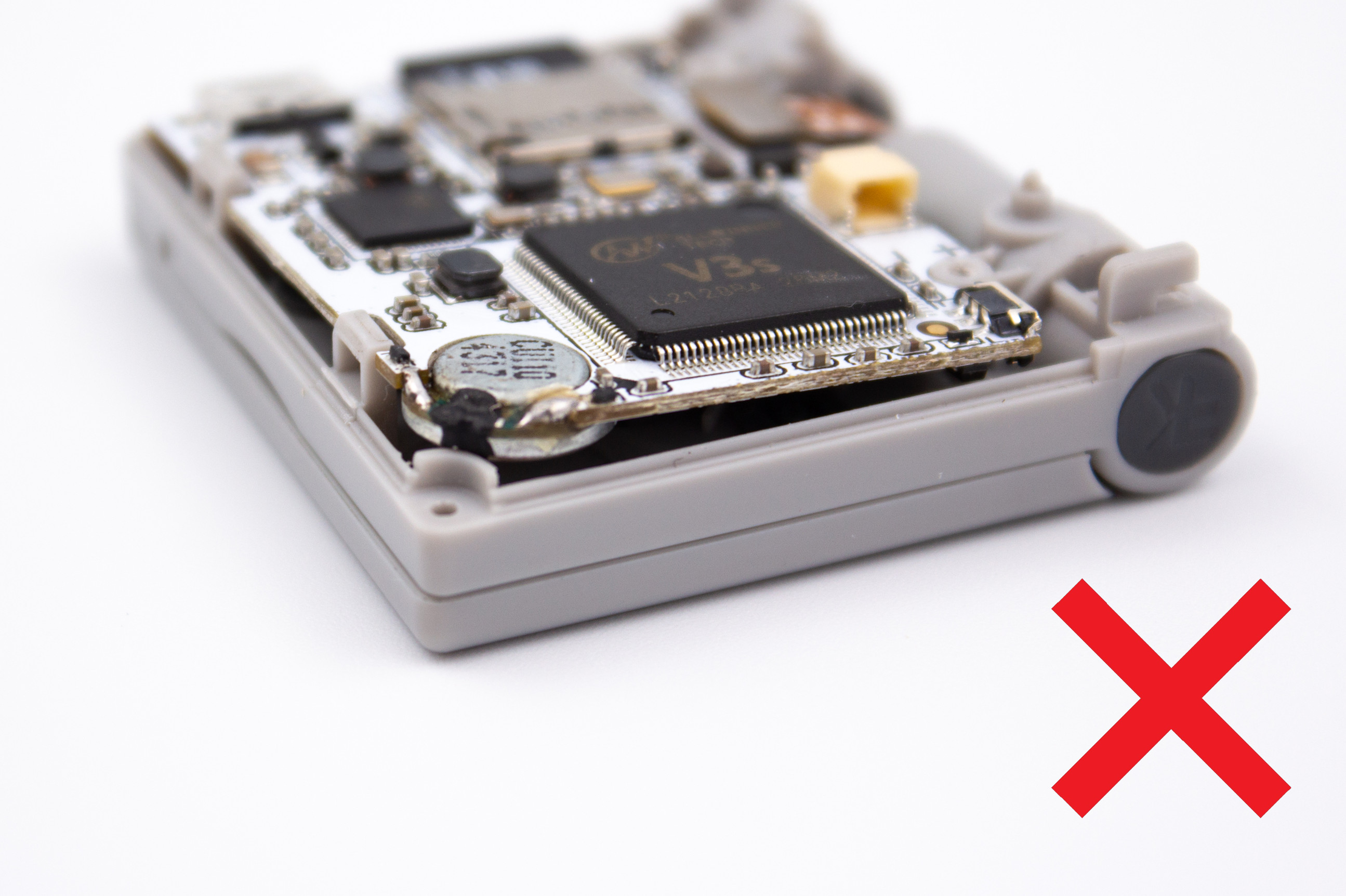
Insert first the speaker into its location in the casing before putting the circuit board back in the case, like in the pictures.
Reassemble the console by following the previous steps in reverse order.
Warning
Be careful not to damage the switches on the circuit board when putting back the L/R plastic buttons.