Audio
Playing audio is absolutely part of the gaming experience!
So for a retro gaming console like the FunKey S, having a decent audio playback is a requirement, despite its lilliputian size.
We discarded the solution of using a piezo-electric buzzer: these can get a loud sound in a small volume, but only at their resonance frequency, so the sound quality is extremely poor.
Turning back to the solutions used in modern smartphones as an example, there are 2 paths to consider:
-
playing audio internally by the mean of speaker(s)
-
playing audio externally by using headphones, with or without a cord
The speakers used in today's smartphones are rather sophisticated and achieve very good performance. However, these are using made-to-measure speakers and cavities, such that they cannot be found and reused as standard parts in a design like ours.
As for the external audio solution, the FunKey S is so small that it is not possible to integrate an audio jack on the PCB to connect headphones! And despite our search, there is no simple and small enough way to integrate Bluetooth to output audio to cordless headphones either.
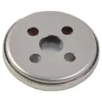
The best solution we have found consists in using a single tiny CUI CDM-10008 speaker, that is able to output 72 dB spl @ 1m from a 0.3W input power, with relatively modest dimensions: 10 mm diameter and only a 2.9 mm thickness, out of which 1.4 mm can be inserted into a PCB hole, thus only having a height above PCB of only 1.5 mm.
Connections are not easy though, since this speaker is meant to have wires soldered to its pads, but we used 2x castellated (half-round plated holes) pads with a placement just over the speaker pads that enables manual soldering between the speaker and the PCB with a solder blob.
Schematic
The audio schematic is simple, as the Allwinner V3s already contains an analog stereo audio codec (coder/decoder): we only have to take one of its headphone output channel (left or right) and feed it to a mono audio amplifier.
We chose the Diodes Inc. PAM8301 chip because of its cheap price, good availability, its more than sufficient output power of 1.5W and its filterless operation, meaning that no bulky series capacitor is required to drive the speaker.
Here is the corresponding schematic:
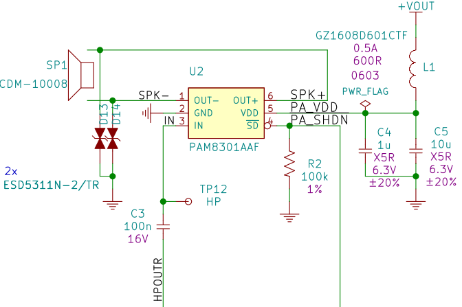
We chose the right headphone channel HPOUTR that is fed to the audio amplifier U2 through a coupling capacitor C3.
The audio amplifier /SD shutdown input is driven by one V3s GPIO (PF7 on pin 100), with a pull-down resistor R2 to disable the amplifier by default.
The audio amplifier power supply is filtered using a ferrite bead L1 in order to eliminate high-frequency digital noise, and decoupled by 2 capacitors C4 and C5, as recommended in the device datasheet.
The speaker SP1 is driven in differential mode in order to get the maximum voltage swing and thus the maximum power available for a given output current.
Two ESD protection TVS diodes D13 and D14 are added, since the speaker may be accessible to the user through the enclosure grid in front of the speaker.