Screen
The second most important part in the FunKey S is certainly its screen: in an overall form factor of roughly 45mm x 45mm x 15mm (1.75" x 1.75" x 0.6"), it has to be comfortable enough to provide a good gaming experience.
In theory, 1.75" would allows to shoehorn a 2.4" (diagonal) square screen, but in practice, 2.4" screens are seldom square and more rectangular in shape.
Unless you are a large manufacturer and selling millions of devices, you are limited to using the existing screen sizes that are available on the market, which most of the time were designed for a long-forgotten specific devices (think of PDAs, MP3 players, clam-shell phones, pods, etc.) and standard aspect ratio are either 1:1, 5:3 or 16:9. Thus, for a given pixel technology, this results in rather standard screen sizes.
So the next available size down are 2" and 1.8", but these screens tend to be quite thick and based on an older technology, so their typical resolution is rather limited @ 128x160 pixels: too small for gamers.
Still going down in size, you can find 1.5" to 1.55" screens with an interesting resolution of 240x240 or even 320 x 320 ("Retina") pixels, but most of them use a fast MIPI DSi interface. These particular screens were popular as they were used in the 6th-generation "square" iPods, but unfortunately, they require a dedicated controller on the host side, which is only available in higher-end SoC.
Another important characteristic of the required screen is that it needs to have a narrow flex cable in order to be rolled into the hinge (like a fly-paper) in order to spread the mechanical flex constraint over several loop rather than at always the same section, resulting in less wear and an expected longer lifespan.
Fortunately, we found this 1.54" LCD screen on AliBaba:
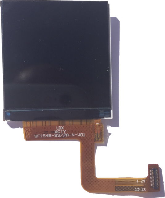
What makes this screen special is its standard SPI interface, which only requires a few wires and thus a narrow flex cable like the MIPI DSi interface, so it is easy to roll into a hinge. But unlike the MIPI DSi one, the SPI interface is readily available on most of the SoC, including the Allwinner V3s.
This 1.54" display features a 240x240 16/18-bit full color pixel resolution and is an IPS display, so the color looks great up to 80 degrees off-axis in any direction.
However, in order to achieve a 50 fps @ 240 x 240 pixel resolution in RGB565 (2 bytes / pixel), this requires a ~44 MHz SPI clock rate, which is rather high.
Once again, we were fortunate as both the V3s CPU and the screen built-in controller (a Sitronix ST7789V) both support this high clock speed (after checking with the manufacturer and despite the controller datasheet that specifies only a serial clock cycle (Write) of 66 ns or 15 MHz!).
We were even luckier as its backlight consists in 3 white LEDs in parallel and not in series, such that no additional step-up DC-DC converter is required, as a standard 3.3V / 60 mA (typical) power supply is sufficient. Of course, we won't be able to drive this current directly from a CPU GPIO and the backlight will require an additional transistor to interface to the LCD backlight.
Its flex cable requires a mating Hirose 0.4 mm pitch DF37NB-24DS-0.4V dual row SMT connector, out of which only one single row is actually used.
Customization
Unfortunately, the flex cable for the stock LCD screen we found does not match our particular FunKey S mechanical design.
For the prototypes, we designed custom flex extension cables for a ~ $100 cost, but we had to design our own custom flex and have this standard screen assembly attached to it for mass production, with a one-time tooling fee of ~ $800.
Schematic
The schematic is quite simple:
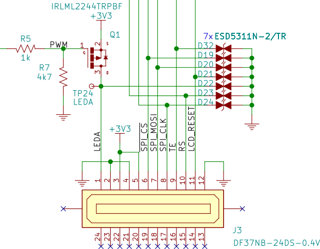
The main component is of course the Hirose screen connector J3, with the following signals:
- LEDA: the backlight LED common Anode connection (+)
- GND
- +3V3 power supply
- /SPI_CS: SPI Chip Select
- SPI_MOSI: SPI Master Out / Slave In
- SPI_CLK: SPI Clock
- TE: Tearing Effect sync signal from the screen
- RS: LCD-specific Register/Memory Select (or Data/Control Select)
- LCD_RESET: LCD Reset
All data signals feature an ESD TVS protection diode D19-D24 and D37, and except for the power supplies and LEDA + LCD_RESET and TE signals, all signals are directly connected to the V3s CPU's SPI interface, so there is not much to say about these.
The LCD_RESET signal is controlled by a V3s GPIO (PB2 on pin 41).
The TE signal from the screen controller is fed to an interrupt-enabled input pin PB1 (pin 40) in order to synchronize the sending of data to the screen with its inactive period in order to avoid the hardware tearing effect.
Backlight PWM
The backlight control requires a few more components: a MOSFET-P transistor Q1 and 2 resistors R5 and R7 to provide its polarization, more on this below.
As the backlight LEDs cathode (-) pin are directly tied to GND within the screen, we need to drive these LEDs "from the high-side", i.e. between the +3V3 power supply and the LEDA pin, so a MOSFET-P transistor is necessary:
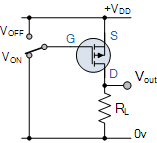
As we want the backlight to be on by default, we need to drive it to GND by default: this is the role of R7. The role of R5 is then to make sure that -Vgs is driven below its threshold voltage and turns off the transistor when the CPU drives a GPIO high.
As an ultimate sophistication, we can drive the backlight from the CPU using one of its built-in PWM controllers PWM0 with a varying duty-cycle, thus controlling the LCD backlight brightness accurately. For this purpose, the other end of the R5 resistor is connected to the PB4 output (pin 43) on the V3s, wich provides this function.